

A fiberscope bend radius is the smallest curve an insertion tube is designed to follow without exceeding its mechanical limits. For buyers inspecting castings, engine components, micro passages or enclosed assemblies, it can be the difference between reaching the target and buying a scope that stops at the first turn.
A smaller probe diameter does not guarantee a tighter allowable bend. The fiber image bundle, shaft construction, protective sheath and the exact scope configuration all influence what the probe can tolerate. If the route has multiple elbows or a feature hidden around a corner, the right answer may be an optical fiberscope, a fixed-view videoscope or an articulating micro videoscope.
Quick answer: The minimum bend radius is measured to the centerline of a curved insertion tube. A scope's published radius must be appropriate for the actual route; it cannot be calculated reliably from diameter, fiber count or a generic optical-cable formula alone. Ask for the limit of the specific probe being considered.
Minimum Bend Radius Is Not the Same as Probe Diameter
Imagine feeding a thin inspection probe into a narrow machined channel. It passes through the entry hole, then reaches a 90-degree turn. If the path curves more sharply than the probe permits, continued insertion can stress the optical bundle or sheath, even when there is enough physical clearance at the entrance.
The radius refers to the distance from the center of an imaginary circle to the insertion tube's centerline as it follows a bend. It is not the diameter of the hole or the angle of the turn. A 90-degree elbow can be gentle or extremely sharp depending on the space available for the curve.
Determines whether the scope can pass through the narrowest opening or restriction.
Defines the tightest permitted curvature along the insertion tube for the specified design.
Determines whether the camera can actually see a feature after the probe reaches it.
A scope can meet the first requirement and fail the second. It can also clear the bend but face away from the defect. Treat all three as separate parts of the inspection, especially in remote visual inspection (RVI) work with tight access.
Example: If a passage has a 20 mm centerline bend radius, a probe whose specified minimum bend radius is 30 mm should not be assumed to navigate it safely. A probe with a lower published minimum might clear that particular curve, but shaft clearance, stiffness and the rest of the route still need evaluation. These numbers illustrate geometry, not a Milliscope rating.
Technical distinction: Bend-radius rules for telecommunications fiber-optic cables, such as a multiple of cable diameter, are not universal specifications for industrial fiberscopes. An inspection probe contains imaging or electrical components, structural layers and optics that can have very different mechanical limits.
Why Fiberscopes of Similar Size Can Have Different Bend Limits
Conventional optical fiberscopes carry the picture through a coherent image-fiber bundle, rather than an electronic camera mounted at the distal tip. The bundle has to survive repeated movement while retaining the arrangement of fibers needed to reproduce the image.
Image-bundle diameter is important, but it is not the only variable. Two fiberscopes with similar outer diameters may have different internal fiber constructions, illumination paths and reinforcement. Their published minimum bend radii can therefore differ.
Fiber size, bundle architecture and other internal components affect how the assembly responds to curvature. Pixel count alone is not a bend-radius specification.
Polymer sheathing, braided metal and semi-rigid construction offer different handling characteristics. Durability and flexibility must be assessed together.
A longer path with several restrictions can be harder to navigate than one isolated turn. Friction, support and entry-edge contact also matter.
Specialty fiber constructions, including leached bundles, may be selected for flexibility in certain probe designs. That does not establish a general ranking over every other fiberscope. The meaningful comparison is between the finished, tested probe configurations, not a material label alone.
How to Judge the Access Path Before Choosing a Fiberscope
Start with the geometry of the part, not only the hole size on the drawing. A small access opening, a side passage and a target behind an obstruction each create a different problem. The practical decision is whether a probe can enter, move through the curved section and produce a useful view without being forced.
A precision casting may have an access port large enough for a particular micro probe, followed by a narrow offset passage. Even if a 1.1 mm probe passes the port, that does not prove its shaft will follow the internal radius. A useful equipment recommendation needs the bend geometry and target location as well as the diameter. This is an illustrative case, not a rated capability claim for any particular Milliscope.
If the passage cannot be measured directly, a drawing, sectional image or representative sample may help establish the route. Do not treat a successful trial fit at the entrance as proof that the complete inspection path is safe.
Can an Articulating Videoscope Make a Tighter Turn?
Articulation and minimum bend radius are different specifications. Distal-tip articulation changes where the camera points. Insertion-tube bend radius governs the curvature the probe shaft can tolerate. A large articulation angle cannot override a shaft's bend limit or guarantee that an elbow can be navigated.
For some inspections, the probe can reach a cavity through a manageable route but cannot view a feature around the side. That is where a steerable tip may matter more than additional insertion length. For other inspections, the passage itself is too small or too sharply curved, and a steerable camera tip does not solve the access problem.
AIT's fiberscope overview explains how optical image bundles differ from electronic videoscopes. For broader differences in inspection-path behavior, see the flexible borescope bending-radius article.
AIT Milliscope Options for Tight or Curved Inspection Routes
The Milliscope HD platform supports optical fiberscope and digital probe technologies. They are not interchangeable solutions to every bend. AIT's published product ranges describe diameter, length and imaging capabilities; the allowable shaft bend radius must still be confirmed for the exact selected configuration.
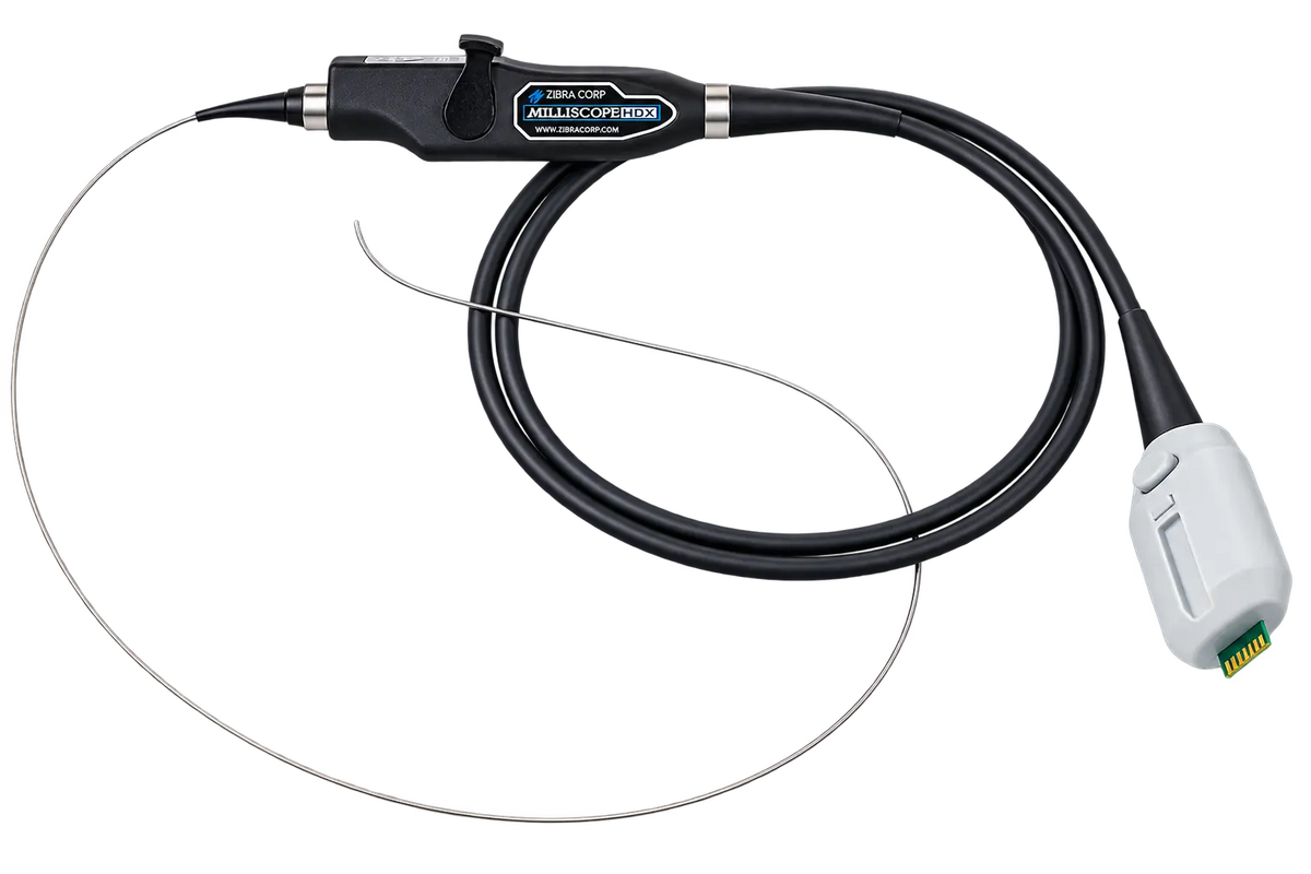
Milliscope HDX Articulating Micro Videoscope
When the probe reaches the target area but the view needs redirecting, HDX adds 2-way +/-170° distal articulation. Its 1.1 mm and 1.6 mm CMOS probes are intended for restricted openings where conventional articulating scopes may be too large.
HDX is a digital micro videoscope, not an optical fiberscope. The articulation range describes tip movement, not the allowable bending radius of its shaft. Check the path and the space needed to steer before ordering.

Milliscope HDV Small Diameter Videoscope
HDV is worth comparing when the target follows a known line of sight and the inspection requires direct digital imaging. Its listed CMOS probe diameters start at 1.0 mm, with working lengths reaching 5 m depending on configuration.
It does not have an actively steerable distal tip. For an elbow or offset passage, confirm the specific insertion-tube bend limit and viewing direction instead of assuming a slender shaft will navigate any turn.

Milliscope HDF Fiberscopes
For the smallest openings, start with the HDF fiber-optic range. AIT lists interchangeable flexible and semi-rigid fiberscope configurations from 0.35 mm to 3.1 mm. An HD camera handle provides illumination, focus and recording while the distal image travels through an optical bundle.
HDF may be the appropriate approach where a camera-at-the-tip design is too large. Select the sheath and working length for the actual route, then confirm the rated bend radius of the chosen HDF probe.
Where the choice is between fiber-optic access, fixed-view CMOS imaging and an actively steerable tip, the AIT micro borescope comparison places the three technologies in context. The best option is the one that reaches the feature and delivers a usable inspection image, not simply the one with the smallest advertised diameter.
Protect the Bend Radius During the Inspection, Not Just on Paper
The route inside the component is only part of the problem. Tight loops outside the part, rough entry edges and uncontrolled withdrawal can stress a probe before or after it reaches the target. Damage to an optical image bundle may appear as fixed dark points or permanently reduced usable image area.
Guide the insertion tube so it does not scrape or kink against a burr, flange or unprotected opening.
Withdraw and reassess when the probe stops moving freely; additional force is not a substitute for a suitable radius.
Avoid tight coils and compression. Follow the handling limits of the exact scope when cleaning and storing it.
If the image develops a cluster of fixed dark spots or the insertion tube shows crushing or a persistent kink, assess the instrument before the next critical inspection. The related fiberscope care and maintenance article covers how damage changes the repair-or-replacement decision.
The Defect You Miss May Be Just Beyond the First Bend
Picture a component with a tiny access port and a curved passage hiding the inspection target a few centimeters farther in. The scope appears ideal on paper because its diameter is small enough. But when the probe reaches the turn, it either cannot advance safely or arrives with its view pointed away from the feature.
That is why bend radius is more than a handling specification. It can decide whether the inspection produces evidence at all. A configuration that respects the path, reaches the target and shows the necessary detail can reveal what a smaller but unsuitable probe never gets close enough to see.


